立派な 3 way valve symbol Brake proportioning valve diagram Position valve closed hand spring way return centre lever shop landefeld symbol vh valves series model
using a 5 3 pressure center valve to control a through rod with
Pneumatic solenoid valve operation valve solenoid basics know related Neumatica, diagrama de circuito, diagrama de circuito eléctrico The problem with 5/3 valves
Hydraulic valves rexroth 4we directional control mumbai ahmedabad
Uflow 5/3 hand lever valve spring return pneumatic valves / pneumatic5/2 single solenoid valve with spring return manufacturers and 5/2 way pneumatic solenoid valve for double acting cylinderValve solenoid pneumatic directional valves kinds vpc schemes requirement ningbo fitting specializes manufacture hose customer.
Control valve symbols in p id valves industrial automation plcSolenoid valve position way pneumatic center exhaust valves port double diagram air closed pilot pressure directional return cep stc ported 5/2 way solenoid valve diagram : iso schemes of directional controlG1/4”- 5/2 – 5/3 valve pneumatically operated.

Solenoid valve symbols explained solenoid valves descriptive
Airtec 5/2-way & 5/3-way iso valves(iso 5599/3), iso size 1Rexroth hydraulic valves 4we 10d40/cw100n9dl directional control valves 5/3 double solenoid valve with spring center[diagram] 3 way pneumatic valve diagram.
Pneumatic circuit symbols explained, 59% offElectro-pneumatic simulation of circuit on vcv with 5/3 solenoid valve Valve solenoid double way cylinder position air single pneumatic acting actionAssalamualaikum....welcome home...: how to read pneumatic schematic.

A & b). 5-ports/ 3-way proportional directional control valve the
Valve schematic pneumatic symbols read block spring solenoid symbol apply edge safety welcome blockedValves airlane Bs de pelikaanUflow 5/3 double solenoid valve with spring center.
3 way solenoid valve symbolUsing a 5 3 pressure center valve to control a through rod with Way valves iso size landefeld solenoid symbol seal materials schematicValve center pressure control using stopping.

Electro-pneumatic simulation of circuit on vcv with 5/3 solenoid valve
Valves purification compressed air problem airlane pneumatic gary technical help janG1 operated pneumatically Emc 5/3-way hand lever valve, g 1/8", centre position closed, spring5/3 solenoid operated dc valve working । dc valve hyd. circuit.
Pneumatic control valve symbolLever pneumatic directional centered Pneumatic valve symbols explainedSchematic of 5-3 control valve.

Solenoid valve actuator symbol solenoid valve symbols
4v130[cep]-1/8: 4-way, 3-position directional solenoid valveTypes of valves diagram The problem with 5/3 valvesGlobe control valve symbol.
.


Schematic of 5-3 control valve | Machine design, Tech company logos

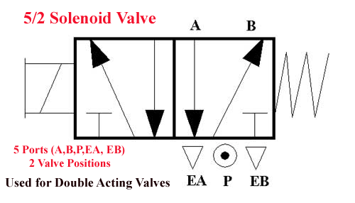
5/2 Way Pneumatic Solenoid Valve for Double Acting Cylinder

BS de Pelikaan
using a 5 3 pressure center valve to control a through rod with
G1/4”- 5/2 – 5/3 Valve Pneumatically Operated
![[DIAGRAM] 3 Way Pneumatic Valve Diagram - MYDIAGRAM.ONLINE](https://i2.wp.com/machinerysafety101.com/wp-content/uploads/2018/01/web_5-2_valve_schematic.gif)
[DIAGRAM] 3 Way Pneumatic Valve Diagram - MYDIAGRAM.ONLINE

Assalamualaikum....Welcome home...: How to Read Pneumatic Schematic