3-way diverting valve piping diagram 5 way valve diagram Emc 5/3-way pneumatic valve, centre position breathing, g 1/4" (pilot
5 Way Valve - [PDF Document]
Valve solenoid double way cylinder position air single pneumatic acting action Image result for hydraulic valve symbols Pneumatic solenoid valve: what is it? how does it work?
Valve way butech ball pneumatic valves hydraulic fittings electric
Manifold way valve procedure diagram valves dpt cr45/3 double solenoid valve with spring center 5 way manifold valve and five way t/ h type direct mount manifold valve5 way valve.
Pneumatic symbols explainedValves actuator positioner instrumentation functions principle instrumentationtools process breather 505f: multi-port 3/4/5-way ball valveValve solenoid pneumatic control directional working animation explained symbols.

Five-port four-way valve diagram
5 way valve diagram5/2 way single solenoid valves [diagram] piping valve diagramPneumatic solenoid valve operation valve solenoid basics know related.
[diagram] pneumatic 3 way valve diagramStructure and function of directional valves Procedure for 5 way manifold valves in dpt5/2 way pneumatic solenoid valve for double acting cylinder.
![5 Way Valve - [PDF Document]](https://i2.wp.com/cdn.vdocuments.mx/doc/1200x630/547ef7bdb37959892b8b56e2/5-way-valve.jpg?t=1704753642)
Machine drawing: rotary four way valves
5-way valve by butechTop 166+ 3 way solenoid valve operation animation Pneumatic schematics symbols explained hydraulic valve reading diagrams automationdirect solenoid schematic wiring actuated plcPneumatic symbols valve control explained pneumatics port ireland.
5 way valvePv techgroup 5l [diagram] pentair 3 way valve diagramFive way valve.
Directional control valve working animation
Pneumatic wege landefeld pneumatikventile baureihe rv 08pXhnotion 5 way 2 position directional solenoid valve hand lever valve 5-way ball valve l pv 5xg1/4"fControl valve positioner circuit diagram.
Solenoid pneumatic centered blocked5/2 single solenoid valve with spring return 5 2 way valve symbol5 way valve diagram.

5 way valve diagram
Electrical schematics explainedHydraulic symbols valves difference direction operated wiring Way valves two valve spool control three flow four direction ports pressure rotary drawing port hydraulics machine other partValve way uncategorized.
.


5 Way Valve Diagram
![[DIAGRAM] Pneumatic 3 Way Valve Diagram - MYDIAGRAM.ONLINE](https://i2.wp.com/www.hafner-pneumatik.com/images/catalog/3-2-way valves.PNG)
[DIAGRAM] Pneumatic 3 Way Valve Diagram - MYDIAGRAM.ONLINE

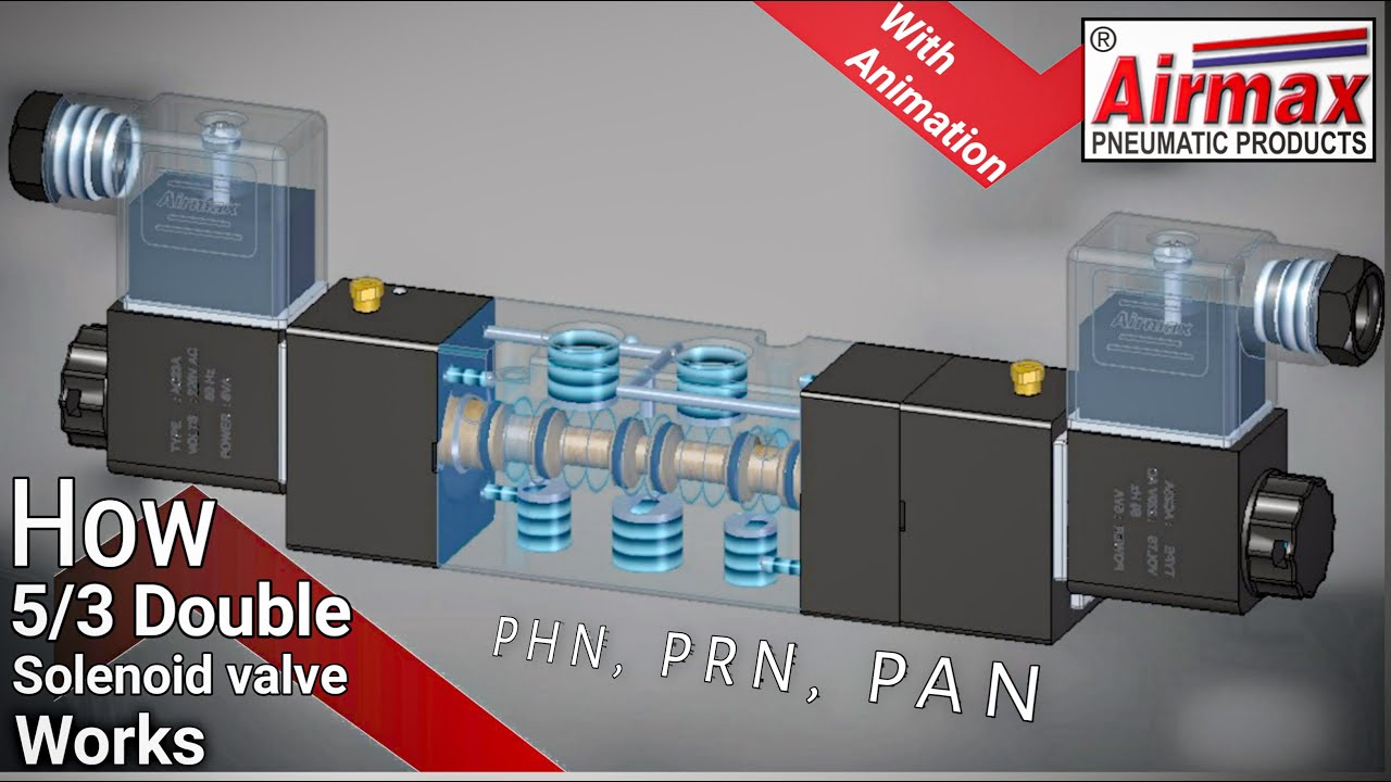
5/3 Double Solenoid Valve With Spring Center | Uflow Pneumatic Valve

Xhnotion 5 Way 2 Position Directional Solenoid Valve Hand Lever Valve

5 Way Valve Diagram

Pneumatic Symbols explained | Pneumatics & Sensors Ireland

Control Valve Positioner Circuit Diagram - Control Valves